If your vehicle types or industry requires tracking additional vehicle information not covered through a vehicle’s diagnostic port, you can use an Auxiliary Input Hub (ACC-AUX).
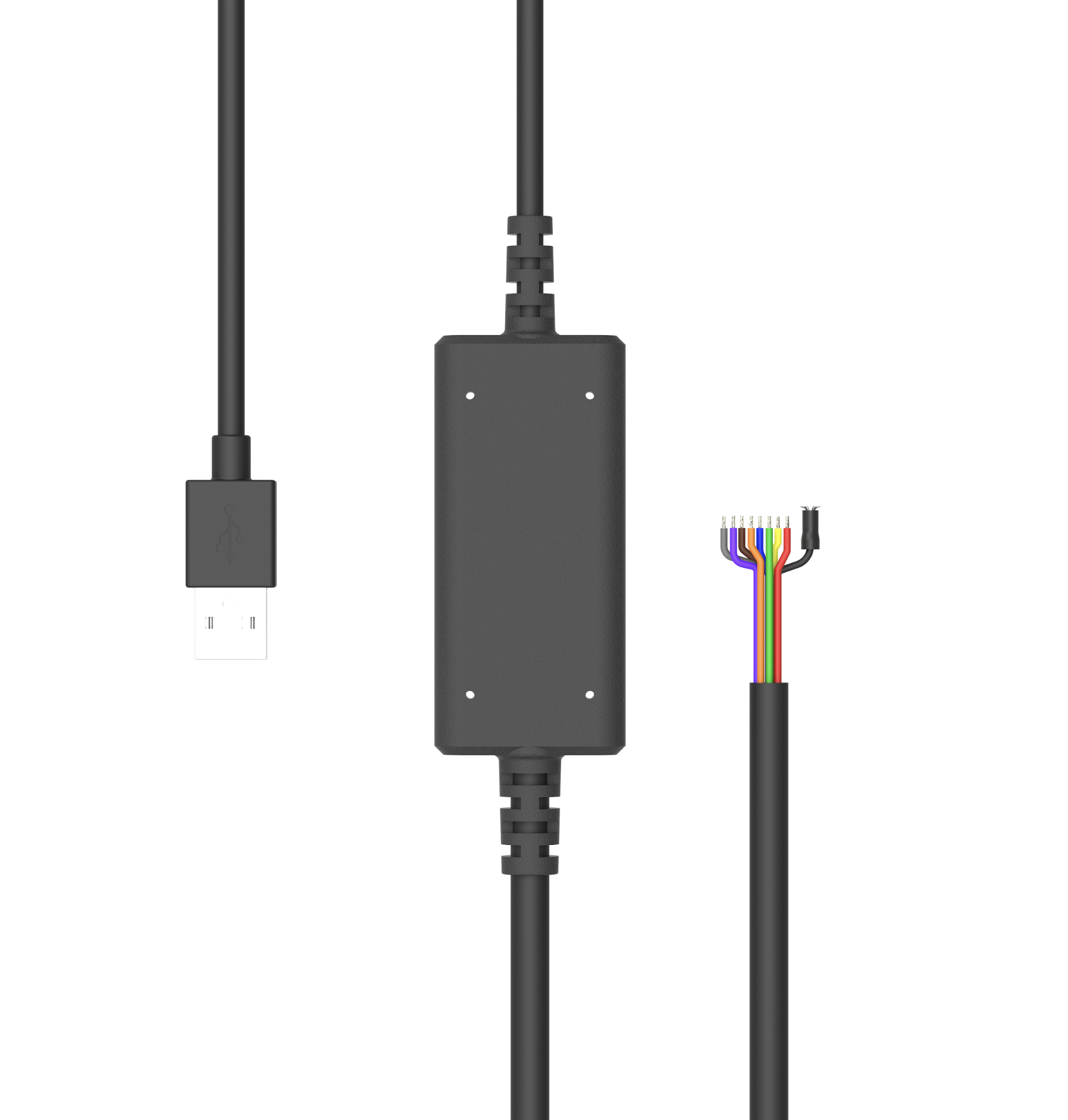 |
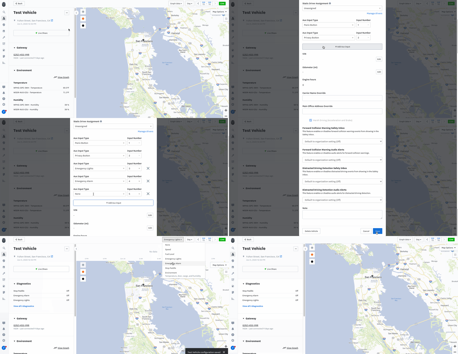
The Auxiliary Input Hub is an easy-to-use, durable accessory that provides up to eight additional digital input lines to the Samsara Vehicle Gateway (VG). The hub is easy to setup and connects to the USB port of a VG. After you connect the hub, all eight lines can be set up in the Samsara dashboard for a wide variety of digital inputs. In the dashboard, these lines can be labeled and tracked over time. Refer to the following image for dashboard activation:
 |
The ACC-AUX is compatible with both VG34 and VG54. When you set up the inputs, ACC-AUX corresponds to input lines 6 through 13 (the CAUX, which is available for the VG54 only, uses input lines 1 through 5).
For more information, see the following resources:
-
Install Guides: VG34 AUX Install Guide and VG54 AUX Install Guide
Each Vehicle Gateway (VG) comes with auxiliary inputs that you can use to connect additional devices to your equipment. You can connect up to two auxiliary lines directly to the VG34. To add additional auxiliary ports, connect an Auxiliary Input Hub (ACC-AUX).
After you install auxiliary devices, the information is available nearly instantly in the Samsara dashboard. View the Equipment Report and your Samsara dashboard Fleet Overview (  ) to see how and where your fleet uses the equipment.
For each auxiliary input you want to connect:
-
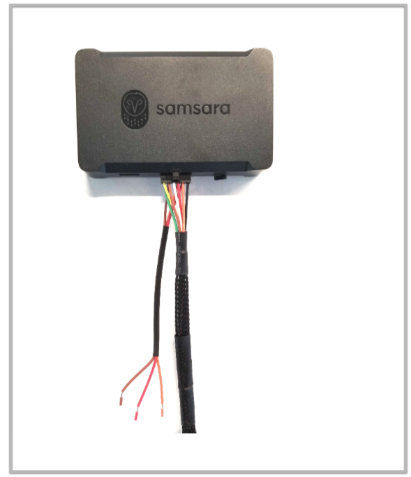
Remove the heat shrink tubing from the pigtail to expose three wires.
-
Locate the wires for Input 1 and Input 2 using the following key:
-
Input 1 = RED
-
Input 2 = ORANGE
-
Unused wire = BROWN
Note
Default OBD cables key:
-
J1939: Input 1 (RED), Input 2 (ORANGE), Unused wire (BROWN)
-
OBDII: Input 1 (GREEN), Input 2 (YELLOW), Unused wire (BLUE)
-
-
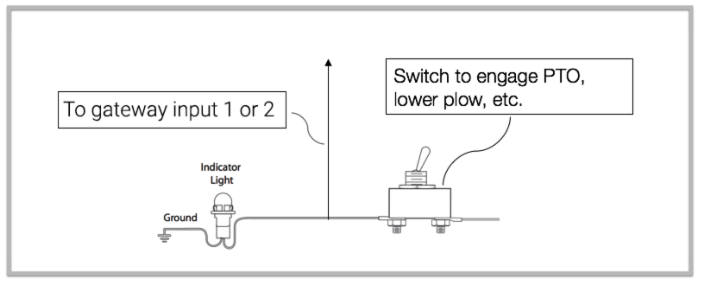
Wire one of these into the circuit of your desired equipment. We recommend wiring to indicator lights, relays, or switches. We recommend using 20-gauge copper wire.
-
Verify the voltage on the input.
When the voltage surpasses 3.3V, the VG considers the device On. A voltage under 3.3V is considered Off. If the voltage remains off, recheck the pin assignments and that the wires are firmly connected.
-
Complete the setup from the Samsara dashboard. See Configure an Auxiliary Input.
Each Vehicle Gateway (VG) comes with auxiliary inputs that you can use to connect additional devices to your equipment. You can connect up to five auxiliary lines directly to the VG54. To add additional auxiliary ports, first connect an 8-Pin Molex Connector (CBL-VG-CAUX) from the diagnostic port on the vehicle to the VG54. Then connect the Auxiliary Input Hub (ACC-AUX) to the VG54.
The cable plugs into the 8-pin Molex Connector on the diagnostic hub and connects to the VG54. It provides the ability to daisy chain multiple accessories using the auxiliary ports (such as the panic or privacy buttons) while still allowing aux inputs into the lines that aren’t already in use.
After you install auxiliary devices, the information is available nearly instantly in the Samsara dashboard. View the Equipment Report and your Samsara dashboard Fleet Overview (  ) to see how and where your fleet uses the equipment.
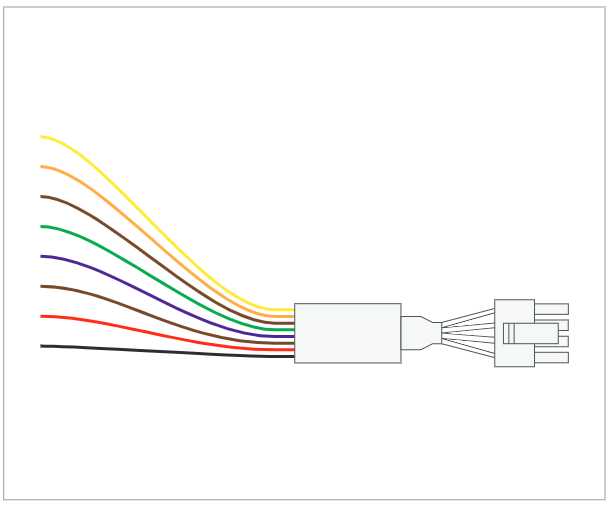
The CBL-VG-CAUX cable is for VG54 only and should be used first.
Use the relevant cable according to the following VG54 auxiliary line input mapping:
|
Input |
Cable |
|---|---|
|
AUX 1 |
CBL-VG-CAUX |
|
AUX 2 |
CBL-VG-CAUX |
|
AUX 3 |
CBL-VG-CAUX |
|
AUX 4 |
CBL-VG-CAUX |
|
AUX 5 |
CBL-VG-CAUX |
|
AUX 6 |
ACC-AUX |
|
AUX 7 |
ACC-AUX |
|
AUX 8 |
ACC-AUX |
|
AUX 9 |
ACC-AUX |
|
AUX 10 |
ACC-AUX |
|
AUX 11 |
ACC-AUX |
|
AUX 12 |
ACC-AUX |
|
AUX 13 |
ACC-AUX |
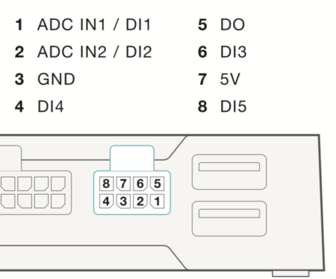
After you install your auxiliary devices, the information is available nearly instantly in the Samsara dashboard. View the Equipment Report and Fleet Overview to see how and where your fleet uses the equipment.
For each auxiliary input you want to connect:
-
Refer to the following table to identify the color wire to use to connect your desired equipment to the auxiliary input.
-
Wire the auxiliary input to connect your lights, relays, switches or other equipment.
We recommend using 20-gauge copper wire.

-
Verify the voltage on the input using a voltmeter.
When the voltage surpasses 3.3V, the VG considers the device On. A voltage under 3.3V is considered Off. If the voltage remains off, recheck the pin assignments and that the wires are firmly connected.
-
Complete the setup from the Samsara dashboard. See Configure an Auxiliary Input.
After you connect an auxiliary input, you can configure the type and pin assignment from the vehicle overview.
 |
-
On the Dashboard Overview, select the vehicle for which you connected an auxiliary input.
-
From the more actions menu ( ... ), select Settings.
-
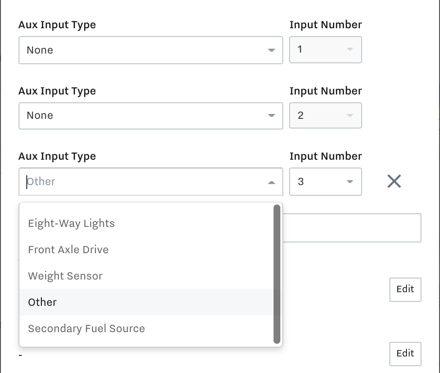
In the Aux Input list, click + Add Aux Input. To configure an auxiliary engine, see Configure an Input as Auxiliary Engine.
-
Select the Aux Input Type or Other if the type doesn't fit into the predefined categories.
-
Select the Input Number that corresponds to the pin assignment.
-
Save the vehicle settings.
After you save the settings, you can view the status of the input in the
Diagnosticsection of vehicle details. To view a graph of diagnostic information for the selected time period above the vehicle map, select the input type from the Graph data drop-down.
To configure an auxiliary input as an auxiliary engine using CBL-AG-APWR cable, use the following workflow:
-
For Aux Input Type, select Auxiliary Engine for Input Number 1.
-
Within Engine hours, select Edit and provide your starting engine hour value.
Value must be greater than 1.
-
Click Save to confirm the changes and update the engine hours.
